Key Takeaways
- The most important conclusions and rationale for Automatic Door Motor
- Specs, compliance, and risk checks worth validating before you commit
- Practical next steps and caveats readers can apply immediately
Why Automatic Door Motor Electrical Issues Matter
The reliability of an automatic door motor is fundamental to the operational continuity, security, and climate control of modern commercial and industrial facilities. When the electromechanical system driving these entryways fails, the consequences extend far beyond minor inconveniences. Electrical faults in these motors can compromise building envelope integrity, leading to significant energy losses and disrupting high-traffic throughput.
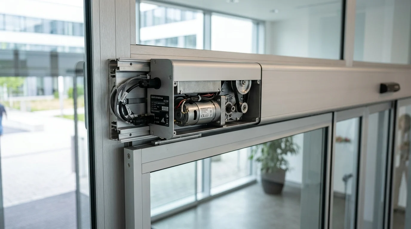
Understanding the root causes of these electrical malfunctions requires a granular approach to electromechanical engineering. An automatic door operator is not an isolated component; it is a complex ecosystem comprising power supplies, microprocessors, sensory inputs, and the drive motor itself. When electrical anomalies occur, they cascade through this ecosystem, necessitating precise diagnostic and remediation strategies to restore optimal function.
Safety and access risks
Electrical failures in an automatic door motor directly impact life safety and accessibility compliance. Under stringent standards such as ANSI/BHMA A156.10 or EN 16005, automatic doors must adhere to strict kinetic energy limits, often restricted to a maximum of 1.69 Joules during the closing cycle. If an electrical fault in the motor control unit bypasses safety sensor inputs or fails to reverse upon obstruction, the door becomes a severe crush hazard.
Furthermore, persistent electrical issues risk non-compliance with the Americans with Disabilities Act (ADA) or equivalent international accessibility mandates. A motor that fails to deliver the required torque due to voltage drops may stall mid-cycle, trapping individuals or completely blocking egress routes during emergencies.
Common electrical warning signs
Facility engineers must recognize the early electrical warning signs before a catastrophic motor failure occurs. Intermittent operation is frequently the first indicator of degraded electrical connections or failing capacitors. Sluggish response times—such as an opening cycle requiring more than 3.0 seconds instead of the specified 1.5 seconds—often point to insufficient current delivery or a failing pulse-width modulation (PWM) drive.
Audible anomalies also serve as critical diagnostic clues. A persistent low-frequency hum from the automatic door motor typically indicates phase loss in AC motors or relay chatter within the control board. Additionally, the smell of ozone or burning phenolic resins is a definitive sign of dielectric breakdown or severe arcing across motor brushes, demanding immediate electrical isolation.
Common Automatic Door Motor Electrical Faults
The architecture of modern entry systems typically utilizes either 24V DC brushed/brushless motors or fractional horsepower AC induction motors. Regardless of the specific topology, the electrical faults that plague an automatic door motor generally fall into predictable categories. Isolating these faults requires differentiating between power generation, logic processing, and electromechanical conversion.
Below is a breakdown of the most frequent electrical failure modes encountered in high-cycle door operators, detailing the mechanisms of degradation that ultimately lead to system downtime.
Power supply and voltage problems
The most pervasive threat to an automatic door motor originates from the facility’s power grid. Voltage sags and surges drastically reduce the lifespan of motor windings and control circuitry. Most 24V DC operators are engineered to withstand a voltage tolerance of strictly +/- 10%. When incoming AC line voltage fluctuates beyond this threshold, the internal switch-mode power supply (SMPS) struggles to maintain stable DC output.
Prolonged exposure to overvoltage conditions degrades the Metal Oxide Varistors (MOVs) designed to clamp transient spikes. Once the MOVs fail, subsequent surges pass directly into the motor’s control board, potentially destroying the H-bridge transistors responsible for reversing the motor’s polarity.
Control board and sensor failures
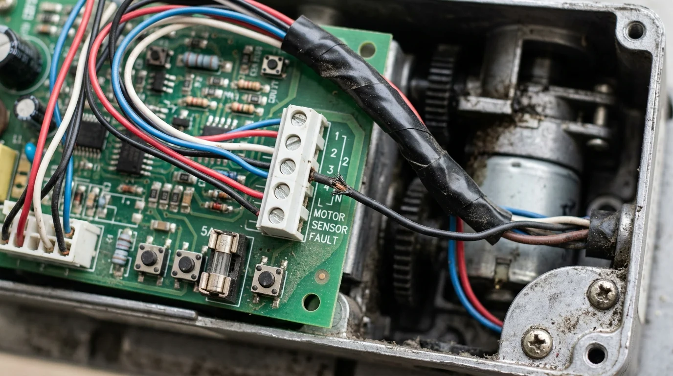
Control boards act as the brain of the automatic door motor, relying on precise inputs from peripheral sensors and internal encoders. A common failure point is the electromechanical relay; after hundreds of thousands of cycles, relay contacts can pit and weld shut due to electrical arcing, causing the motor to drive continuously against the door frame and trip the 5A slow-blow thermal fuse.
Sensor and encoder failures represent another critical logic fault. Brushless DC (BLDC) motors rely on Hall-effect sensors or quadrature encoders to report rotor position. If the encoder cable suffers electromagnetic interference (EMI) or wire fatigue, the controller loses the pulse train. Without accurate position feedback, the motor will exhibit erratic hunting behavior or trigger a fatal positioning error code.
Motor overheating and insulation breakdown
Motor overheating is typically a byproduct of exceeding the specified duty cycle or operating the door against excessive mechanical friction. When an automatic door motor draws higher-than-rated current (e.g., pulling 8 Amps instead of a nominal 3 Amps), the internal temperature rises rapidly. This thermal stress degrades the winding insulation.
Most commercial operators utilize Class B (130°C) or Class F (155°C) insulation. Once this thermal threshold is breached, the dielectric strength of the enamel coating breaks down, leading to turn-to-turn shorts within the stator. Insulation resistance dropping below 1 Megohm is a definitive indicator of impending motor death.
| Fault Category | Affected Component | Typical Root Cause | Primary Symptom |
|---|---|---|---|
| Voltage Irregularity | Power Supply / SMPS | Grid surges, degraded MOVs | Blown fuses, burned varistors |
| Logic / Signal Loss | Control Board / Encoder | EMI, wire fatigue, relay arcing | Erratic movement, hunting behavior |
| Thermal Breakdown | Motor Windings | Excessive duty cycle, high friction | Short circuits, dropping below 1 Megohm |
How to Diagnose Electrical Problems
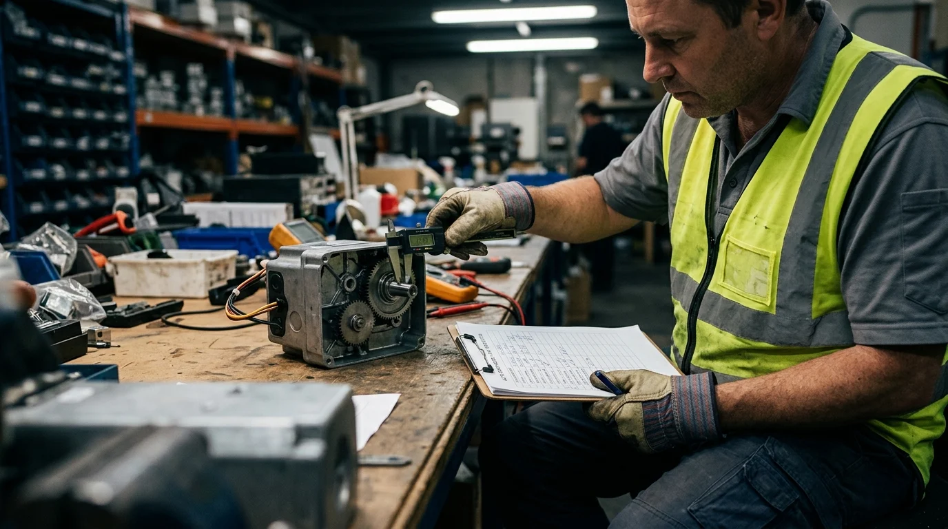
Accurate diagnostics prevent the costly and unnecessary replacement of functional components. Troubleshooting an automatic door motor requires a systematic approach, moving from macro-level power inputs down to micro-level component behaviors. Facility technicians must utilize calibrated digital multimeters (DMMs) and, in complex cases, oscilloscopes to trace electrical anomalies.
Blindly swapping parts often masks the true root cause, leading to repeat failures. A rigorous diagnostic protocol ensures that the specific electrical fault is isolated and quantified against the manufacturer’s engineering specifications.
Pre-replacement testing steps
Before dismantling the automatic door motor, technicians must perform a comprehensive pre-replacement evaluation. The first step is verifying the incoming line voltage under load to ensure it does not dip below the required operational threshold. Next, the technician must isolate the main power and perform a visual inspection of the control board for bulging electrolytic capacitors or carbon tracking near the terminal blocks.
Continuity testing of all peripheral wiring harnesses is essential. Technicians should verify that safety sensors, radars, and activation pads are delivering the correct dry-contact closures or voltage signals. For the motor itself, applying a direct, regulated 24V DC bench supply (bypassing the control board) can quickly determine if the fault lies within the motor windings or the logic controller.
Key measurements and fault codes
Quantifiable measurements are the foundation of expert diagnostics. When testing a 24V DC brushed automatic door motor, the armature winding resistance should typically measure between 2.0 and 10.0 ohms. A reading of less than 1 ohm indicates a dead short, while an infinite reading indicates an open circuit, likely due to completely worn carbon brushes.
For insulation integrity, a Megohmmeter (Megger) test performed at 500V DC is standard practice; the reading must exceed 1 Megohm to ground. Additionally, modern controllers utilize CAN bus or RS485 communication protocols that output specific hexadecimal fault codes. Reading these codes via a diagnostic terminal—such as identifying an ‘E01’ for continuous overcurrent or ‘E04’ for missing encoder pulses—rapidly narrows down the troubleshooting matrix.
How to Fix and Prevent Electrical Problems
Remediation of electrical faults in an automatic door motor spans a spectrum from simple component-level repairs to comprehensive preventive maintenance strategies. The objective is to restore the electromechanical integrity of the system while mitigating the risk of future electrical anomalies.
By implementing targeted repair actions and establishing a rigorous maintenance cadence, facility managers can significantly extend the operational lifecycle of their entryway assets, ensuring compliance with safety standards and maximizing return on investment.
Repair actions for common components
For brushed DC motors, the most common repair action is the replacement of carbon brushes. Brushes should be inspected and replaced if their length has worn down to less than 6mm, as operating below this threshold risks the brush shunts scoring the commutator. When addressing control board issues, technicians can often swap blown electrolytic capacitors (commonly 4700µF, 50V rated) or reflow cold solder joints on high-current relay pins.
If the automatic door motor utilizes an external encoder, replacing a frayed wiring harness or realigning the optical sensor wheel can resolve positioning faults without requiring a full motor replacement. However, if the motor windings exhibit turn-to-turn shorts, rewinding is rarely cost-effective for fractional horsepower units, necessitating a complete motor swap.
Preventive maintenance practices
Preventive maintenance is the primary defense against electrical failure. A biannual maintenance schedule should include verifying the torque on all electrical terminal blocks; control wiring terminals should typically be torqued to 0.5 Nm to prevent high-resistance connections that generate heat and voltage drops.
Technicians must also clean the motor commutator and blow out carbon dust, which can become conductive and cause low-level short circuits across the logic board. Furthermore, ensuring the mechanical tracks and rollers are properly lubricated reduces the mechanical load on the automatic door motor, directly lowering its continuous current draw and operating temperature.
When to repair, retrofit, or replace
Deciding between repair, retrofit, or replacement relies on the industry-standard ‘50% rule’: if the cost of an electrical repair exceeds 50% of the cost of a new operator, replacement is the fiscally responsible choice. Facility managers must also evaluate the unit’s position in its expected lifecycle.
A standard brushed automatic door motor is typically rated for 1 to 2 million cycles, whereas a modern brushless DC (BLDC) motor can easily exceed 3 to 5 million cycles. If a brushed operator facing electrical failure has already surpassed 1.5 million cycles, repairing the electrical fault is a stopgap measure, and a full retrofit to a BLDC system is highly recommended.
How Facility Managers Should Decide After Repeated Failures
When a specific entryway experiences repeated electrical failures, facility managers must pivot from reactive repairs to strategic capital planning. Chronic faults often indicate a fundamental mismatch between the installed automatic door motor and the environmental or operational demands of the facility.
Navigating these decisions requires a comprehensive analysis of technical specifications, total cost of ownership (TCO), and the logistical realities of supply chains and facility downtime.
Specification and compatibility factors
Repeated motor burnouts typically necessitate a specification review. Managers must ensure the automatic door motor is rated for the actual door leaf weight. If a motor rated for 100 kg per leaf is driving a 150 kg architectural glass door, the continuous overcurrent will inevitably cause rapid electrical failure. Upgrading from a legacy brushed system to a high-torque BLDC motor offers superior thermal management and eliminates brush wear entirely.
Compatibility is also paramount when selecting retrofit kits. The new motor and control board must seamlessly integrate with existing fire alarm systems (for emergency drop-out) and building management systems (BMS). Ensuring the controller supports the correct voltage inputs and signaling protocols (such as dry contacts or 0-10V analog inputs) prevents costly integration delays.
Cost, downtime, and spare parts considerations
Evaluating TCO involves balancing upfront capital expenditure against the cost of operational downtime and spare parts availability. Sourcing proprietary OEM replacement boards for older automatic door motors can incur lead times of 2 to 4 weeks, leaving secure entryways physically propped open or locked down.
Conversely, standardizing on non-proprietary retrofit kits often guarantees parts availability within 24 to 48 hours. Facility managers must weigh the immediate disruption against long-term reliability, using lifecycle extension metrics to justify the initial expenditure to stakeholders.
| Strategy | Initial Cost Band (USD) | Typical Downtime | Expected Lifecycle Extension | Spare Parts Lead Time |
|---|---|---|---|---|
| Component Repair | $150 – $400 | 1 – 3 Hours | 6 – 12 Months | 1 – 3 Days |
| Electronic Retrofit | $800 – $1,500 | 4 – 6 Hours | 3 – 5 Years | 24 – 48 Hours |
| Full Header Replacement | $2,500 – $4,500 | 1 – 2 Days | 10+ Years | 2 – |
Frequently Asked Questions
Why does an automatic door motor run intermittently?
Intermittent operation usually points to loose wiring, unstable voltage, or a failing control board relay. Check terminal tightness, measure input/output voltage, and inspect the board for heat damage before replacing the motor.
What causes a low hum from an automatic door motor?
A low hum often means poor power delivery, relay chatter, or motor winding stress. Shut off power, verify supply voltage is within tolerance, and inspect the control board and connections for arcing or wear.
How can I tell if the problem is the sensor or the motor?
If the door gets power but moves erratically, stops mid-cycle, or shows positioning errors, the sensor or encoder may be at fault. If it is silent or overheats quickly, test the motor and power supply first.
How do Beifan-style microcomputer door operators help reduce electrical faults?
Microcomputer-controlled speed adjustment helps reduce overload, harsh starts, and unstable movement. Used correctly, modes like hold-open or half-open can also lower cycle stress and extend motor and control board life.
When should an automatic door motor be replaced instead of repaired?
Replace it when there is repeated overheating, insulation smell, burnt windings, or recurring board damage after repairs. For high-cycle sites, replacement is usually more reliable than repeated electrical patchwork.